
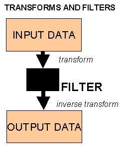
Seismic data is recorded into what is termed the time-domain. Several common processing routines transform the data into a new domain, perform some kind of operation and then the inverse routine is used to reverse the transform. The purpose of this procedure is to find a domain where signal can be more easily be separated from noise and filtered or muted out. It is often easier to understand noise types and design a filter with the data transformed into the new domain. A filter is applied to data to alter it in a manner calculated to improve its quality in some way by removing noise (unwanted signal). Muting refers to the process of zeroing unwanted data samples to improve data quality and is therefore a crude filter. In theory, if no operation were performed the output would be identical to the input, however this is not always the case in practise because of approximations made in the transform stages. Another reason for using transforms is computational efficiency. In the recent past when computer power was minimal and computer time was expensive then the often minimal loss in accuracy (or introduction of artifacts) using transforms was considered acceptable compared to the computer time saved. Modern computer systems may not need such transforms to perform operations efficiently, however much of the historical literature will be written from this perspective. The user is unlikely to notice the differences on the final processed data whichever way the routines are implemented, although some of the parameter choices may differ in order to minimise artifacts.
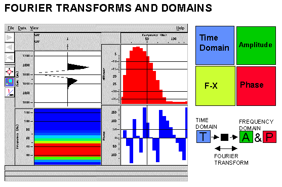
The Fourier Transform is by far the most important used in seismology. Fourier's theory states that a given signal can be synthesised as a summation of sinusoidal waves of various amplitudes, frequencies and phases. Using the Fourier Transform a time domain signal is transformed to the frequency domain where it is equivalent to an Amplitude Spectrum and a Phase Spectrum. The adjacent figure shows a simple time domain wavelet transformed into it's frequency domain components. The F-X or w -x domain is also shown. Basically this is a one-dimensional Fourier Transform over time of usually of a gather or group of traces (hence the x-dimension). A process operating in this domain will mix or alter the amplitude spectra of the group of traces before the inverse transform is applied. Since there is only a single trace in the figure the F-X domain here just represents a different view of the amplitude spectrum. The figure was created with PROMAX routine Interactive Spectral Analysis.
Many operations e.g. bandpass frequency filtering are easier to understand in the frequency domain. The Discrete Fourier Transform (DFT) is applied to a digitised time series, and the Fast Fourier Transform (FFT) is a computer algorithm for rapid DFT computations. The latter imposes the restriction that the time series must be a power of two samples long e.g. 512, 1024 which is usually achieved by padding seismic traces with extra zeros.
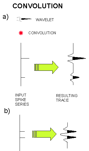
CONVOLUTION: Is a mathematical way of combining two signals to achieve a third, modified signal. The signal we record seems to respond well to being treated as a series of signals superimposed upon each other that is seismic signals seem to respond convolutionally. The process of DECONVOLUTION is the reversal of the convolution process. Convolution in the time domain is represented in the frequency domain by a multiplying the amplitude spectra and adding the phase spectra. The adjacent figure shows a spike series representing an acoustic impedance response from the earth which is convolved (*) with a source wavelet to produce a resulting seismic signal which is measured. In principal by deconvolving the source wavelet we could obtain the earth's reflectivity. However, noise (unwanted signal) and other features are also present in the recorded trace and the source wavelet is rarely known with any accuracy. In the figure (a) the spikes are sufficiently separated that the convolution just results in a duplication of the input wavelet at the spike times and with the spike amplitudes. The convolution process just involves multiplying every sample of the spike series by the input wavelet and adding all the results. In (b) the spikes are closer together and interference occurs in the resulting trace. If the wavelet were known the input spike series could be discovered by the deconvolution process. The convolutional model of the seismic trace states that the trace we record is the result of the earth's reflectivity (what we want) convolved with the source wavelet (and it's ghosts), multiples, the recording system and some noise.
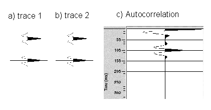
CROSS-CORRELATION: Is a statistical measure used to compare two signals as a function of the time shift (lag) between them. AUTOCORRELATION is a special case where the signal is compared with itself for a variety of time shifts (lags) and is particularly useful for detecting repeating periods within signals in the presence of noise. The autocorrelation function is often normalised so that its maximum value at zero lag is 1 (where the signal is correlated with itself). The adjacent figure shows the autocorrelation function of a simple trace with two separated peaks. Figure (c) shows that the autocorrelation clearly identifies the repeated wavelet in the input time series by the peak at 100ms. The autocorrelation has a zero-phase spectrum. Both auto- and cross-correlation functions are required in the suppression of multiple reflections by predictive deconvolution.
A wavelet is a term used to describe a short time series (typically less than 100 samples) which can be used to represent, for example, the source function. As previously shown, the wavelet can be studied as a time series in the time domain or in the frequency domain as an amplitude or phase spectrum. For any amplitude spectrum there are an infinite number of time domain wavelets which can be constructed by varying the phase spectrum. There are two special types of phase spectra of specific interest.
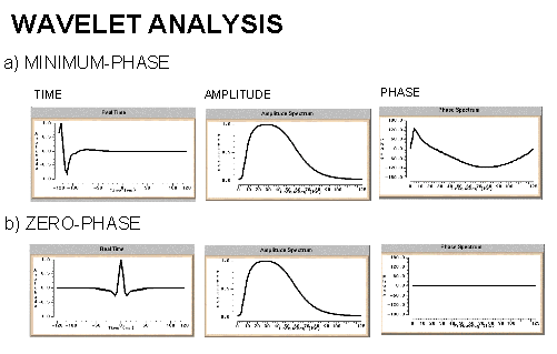
The minimum phase wavelet has a short time duration and a concentration of energy at the start of the wavelet. It is zero before time zero (causal). An ideal seismic source would be a spike (maximum amplitude at every frequency), but the best practical one would be minimum phase. It is quite common to convert a given wavelet source wavelet into it's minimum phase equivalent since several processing stages (e.g. predictive deconvolution) work best by assuming that the input data is minimum phase. The maximum phase wavelet is the time reverse of the minimum phase and at every point the phase is greater for the maximum than the minimum. All other causal wavelets are strictly speaking mixed-phase and will be of longer time duration. The convolution of two minimum phase wavelets is minimum phase. The zero-phase wavelet is of shorter duration than the minimum phase equivalent. The wavelet is symmetrical with a maximum at time zero (non-causal). The fact that energy arrives before time zero is not physically realisable but the wavelet is useful for increased resolving power and ease of picking reflection events (peak or trough). The convolution of a zero-phase and minimum phase wavelet is mixed phase (because the phase spectrum of the original minimum phase wavelet is not the unique minimum phase spectrum for the new modified wavelet) and should be avoided.
A special type of wavelet often used for modelling purposes is the Ricker wavelet which is defined by it's dominant frequency. The Ricker wavelet is by definition zero-phase, but a minimum phase equivalent can be constructed. The Ricker wavelet is used because it is simple to understand and often seems to represent a typical earth response.
WIENER FILTERING: To find the filter to shape a wavelet to another wavelet is not an exact process, but the filter which produces the closest result can be obtained by a mathematical technique known as least squares. The Wiener filter is that which best (in a least squares sense) shapes a given wavelet to a desired wavelet. Applications include shaping a source wavelet to it's minimum phase equivalent, shaping a wavelet within the data to a spike (to improve resolution) or to shape a time-series with multiples to one without multiples (predictive deconvolution). Without going into the mathematics it turns out that the filter is found by dividing the cross-correlation of the input with the desired output by the auto-correlation of the input. This solution sets up a series of simultaneous equations which are solved rapidly in the computer by matrix inversion using the Levinson algorithm. A certain percentage of noise (called white noise or white light) is added to stabilise the inversion program.
A two-dimensional Fourier transform over time and space is called an F-K (or K-F) transform where F is the frequency (Fourier transform over time) and K refers to wave-number (Fourier transform over space). The space dimension is controlled by the trace spacing and (just like when sampling a time series) must be sampled according to the Nyquist criterion to avoid spatial aliasing. Temporal Aliasing was previously discussed. In the F-K domain there is a two-dimensional amplitude and phase spectrum but usually only the former is displayed for clarity with colour intensity used to show the amplitudes of the data at different frequency and wave-number components. Several noise types such as groundroll or seismic interference may be more readily separated in the FK amplitude domain than the time-space domain and therefore will be easier to mute before the inverse transform is applied.
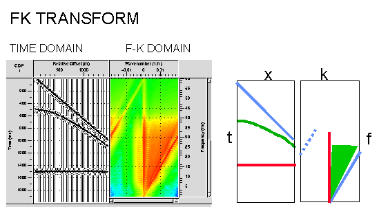
In the adjacent figure the flat event on the synthetic CMP gather shown in red maps onto the vertical K=0 axis. The event coloured in red is seen to have a dominant frequency content of 5-40Hz. The dipping refraction shown in blue maps to a dipping blue event and this event becomes spatially aliased above 30Hz where it shows reverse dip (note the total frequency content is the same since it is the same synthetic wavelet). The FK domain shows the spatial aliasing clearly whereas in the time domain it is more difficult to spot by eye. The curved event shown in green maps to a range of dips in FK. Therefore the FK transform may be described as decomposing the input data into a series of straight lines which map to straight lines in the FK space, hence a range of dips in time can be identified in FK and suppressed by muting. However it is easily seen that if a filter was designed to remove the RED event it would be difficult to avoid filtering parts of the GREEN event (the horizontal portions on the near offsets). It is easy to introduce artifacts using this technique by application of filters with too steep slopes - considerable smoothing is often required at the filter edges. The PROMAX routine (FK ANALYSIS) used to produce the figure allows interactive picking of filters and will display the results interactively for quality control purposes.
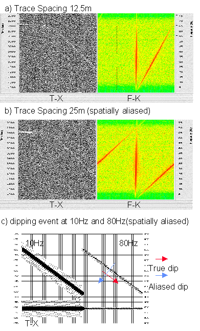
Spatial aliasing, is a common problem to be considered when performing data processing. One way to limit the spatial aliasing of the previous figure would be to remove frequencies above 30Hz. This would be wasteful of primary signal. The trace spacing is also important. Consider the adjacent figure (a) & (b) showing an event of 70Hz dipping at 20 degrees. Sampling every 12.5m samples the signal properly, but at 25m the signal becomes spatially aliased and appears to show reverse dip which confuses interpretation (as well as many processing algorithms such as migration).
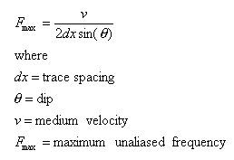
Reverse dip is shown more clearly in figure (c) where the dip of the dipping event becomes confusing when high frequencies are present. This effect is often more apparent to computer algorithms than the human eye which tends to de-alias seismic data. The formula for determining the maximum frequency which can be handled without spatial aliasing is given by:

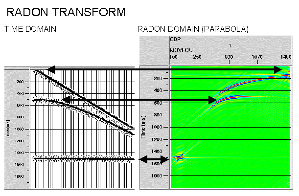
Strictly speaking the Radon transform is a generic mathematical procedure in which the input data in the frequency domain are decomposed into a series of events in the RADON domain. Whichever curve type is chosen will map to a point. Note this is similar to Fourier decomposition but using more complex functions than sinusoids. Common geophysical usage however refers to the particular case where the input data is decomposed into parabolas (or sometimes hyperbolas) since this transform can be computed efficiently. The adjacent shows such a transformation and illustrates that the RADON domain can be more accurate for filtering curved rather than dipping events than the FK domain - the technique is now very commonly used for multiple suppression. Artifacts are also reduced. Parameters required are the number and spacing of parabolas (often referred to as P traces) and the maximum frequency to be transformed. The PROMAX routine (RADON ANALYSIS) is not as interactive as the FK routine.
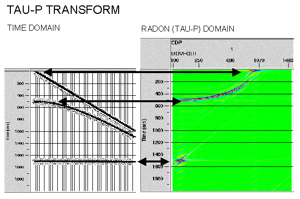
The TAU-P transform is another special case of RADON transform where the data are decomposed as a series of straight lines which map to points in the tau-p domain. Hyperbolic events (e.g. those in shot gathers) map to elliptical curves in Tau-P. This process also used to be referred to as slant-stacking since to produce the tau-p domain the input data may be stacked along a series of straight lines. The tau-p process is becoming common prior to predictive deconvolution for multiple suppression since this performs more accurately in the tau-p domain. The tau-p transform may also be used to optimally isolate and filter guided waves, refractions and types of interference. Filtering in the tau-p domain is usually more expensive than in the F-K domain, but can produce better quality results.