The purpose of seismic processing is to manipulate the acquired data into an image that can be used to infer the sub-surface structure. Only minimal processing would be required if we had a perfect acquisition system. Processing consists of the application of a series of computer routines to the acquired data guided by the hand of the processing geophysicist. There is no single "correct" processing sequence for a given volume of data. At several stages judgements or interpretations have to be made which are often subjective and rely on the processors experience or bias. The interpreter should be involved at all stages to check that processing decisions do not radically alter the interpretability of the results in a detrimental manner. A further chapter provides guidelines for specific processing problems encountered in various geological provinces.
Processing routines generally fall into one of the following categories:
In this chapter we briefly describe working with contractors and define a basic 2D marine processing flow which contains links to the more specialised descriptions of various processing routines.
Today most processing is carried out by contractors who are able to perform most jobs quickly and cheaply with specialised staff, software and computer hardware. There are currently five main contractors who are likely to have an office or an affiliation almost anywhere in the world where oil exploration is taking place. In addition there are many smaller localised contractors principally in London and Houston, and also some specialised contractors who concentrate on particular processing areas. These are summarised in the following table.
|
CONTRACTOR |
SIZE |
SPECIALITY |
|
CGG |
Large |
3D, PSDM, Land. |
|
WESTERN GEOPHYSICAL |
Large |
3D |
|
GECO-PRAKLA |
Large |
3D, Land |
|
PGS |
Large |
3D |
|
VERITAS (former DIGICON) |
Large |
3D, 2D, Land. |
|
ENSIGN |
Moderate |
3D marine, some 2D |
|
SPECTRUM |
Moderate |
2D, basic 3D, scanning |
|
GEOTEAM |
Small |
2D |
|
ROBERTSONS |
Small |
2D, basic 3D |
|
ODEGAARD |
Specialised |
Inversion |
|
JASON |
Specialised |
Inversion |
|
GXT |
Specialised |
PSDM (2D & 3D) |
|
PARADIGM |
Specialised |
PSDM (2D & 3D) |
In order to place a contract with one of the contractors, a budget and AFE (authorisation for expenditure) should be in place. The processing manager (or nominated staff) can then raise a CRD (contract request document) with contracts staff in Aberdeen. A large contract would typically be tendered to all the major and a subset of the minor contractors and the successful bid chosen by the contracts engineer and processing manager using criteria such as cost, turnaround, quality and specialised knowledge. Amerada Hess Limited has call-off contracts with all the major contractors such that the tendering, evaluation and award process can be completed in less than two weeks if required. For typical tasks most of the major contractors can be considered approximately equivalent, although to a certain extent this does depend on individual personnel involved. For certain smaller specialised projects a single-source purchase order may be raised, subject to appropriate justification. Depending on project size a typical 2D project may take 4-12 weeks and a typical 3D project 4-12 months to complete.
It is usual for the processing manager or nominated representative to follow the progress of the contract and liase with the exploration staff during the duration of the contract. It is usually the responsibility of the exploration staff to keep partners informed of progress. The contractor will typically produce a schedule at the beginning of a project and will almost certainly fail to keep to it. The schedule should include all appropriate testing, meetings, production and final copies (including reporting) for the project.

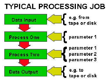
A processing flow is a collection of processing routines applied to a data volume. The processor will typically construct several jobs which string certain processing routines together in a sequential manner. Most processing routines accept input data, apply a process to it and produce output data which is saved to disk or tape before passing through to the next processing stage. Several of the stages will be strongly interdependent and each of the processing routines will require several parameters some of which may be defaulted. Some of the parameters will be defined, for example by the acquisition geometry and some must be determined for the particular data being processed by the process of testing. It is reiterated that the parameter choice is often subjective. The best rule is to keep things a simple as possible unless forced to do otherwise.

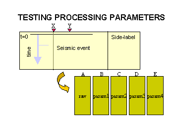
For the unknown parameters the processor will establish a series of tests which usually take a representative sample of the data (e.g. from X to Y in the figure) and subject it to several parameter choices (B,C,D,E). The processor and interpreter will then compare the test panels and pick the parameter which they judge best corrects the data by comparing the various tests. The bulk of the data will then be processed with these parameter choices (production processing). When production is underway, the next processing stage can be tested. Often tests are constructed which trial several parameters simultaneously and it can become very easy to design tests which are too complicated and are consequently poorly diagnostic. The general rule is "the simpler the better". Particular care must be taken when scaling the tests (e.g. to raw panel A) to ensure that fair comparisons are made between them - a so called "apples to apples" comparison.
For a 2D project typically a dip line and a strike line would be chosen for testing. Sometimes parameters would be checked on other lines too. A brute stack would often be produced for each 2D section, sometimes onboard the acquisition vessel. This brute stack typically uses a single set of parameters (particularly a single velocity function) for the entire data volume but may be very useful for highlighting areas where changing geology or other conditions may require different seismic processing parameters. Some tests would be performed on whole lines (ideal), but some tests may be performed on small areas e.g. 500 trace segments.
Often a zone of interest is defined by the interpreter so that routines can be concentrated in this area. Note that this can result in degradation of other parts of the section. This can be a significant problem when processing a regional 3D survey when only a single 2D line is chosen for testing.
For 3D projects several representative 2D lines should be chosen for initial testing. As soon as the data grid has been established then several crosslines should also be selected for testing. Most contractors can now extract crossline information following the first production processing stage. Crosslines can be particularly useful for confirming test parameters. In addition any onboard processed data (if available) should be used.
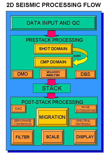
A typical processing sequence has been established throughout the years for marine 2D processing. The sequence is displayed graphically in the following figure. Click on any item in the sequence or figure to obtain more detailed information or proceed to a later written description of the sequence.

Phases 1 to 5 are described as prestack processes. The stack process typically reduces the data volume to be processed by 30 to 60 times so that post-stack processes are often much quicker to apply. Post-stack processing will be concentrated on in this course following a discussion of key prestack processes such as velocity analysis.
Alternative processing flows can be selected from the following list (not complete as of 29/1/99).
The full prestack processing sequence follows:
Items in () are optional.
Items in () are optional, but are almost always applied.
Items in () are optional, but are almost always applied.
Almost every seismic processing system will have it's own format for seismic trace data, velocity files, horizon files etc. This can lead to considerable confusion. A number of standard interchange formats are used by Amerada Hess. These are: